This article targets an advanced audience who are already familiar with the 3D printing. In this article I will try to collect some information I haven’t found written down in a single place yet. In particular, a lot of the information is seemingly only available in the form of YouTube videos that take a long time to get to the point.
This article assumes some familiarity with CAD and 3D printing. Basic concepts and terminology is not explained.
Basics of vase mode
With that out of the way what is this about? Vase mode is a printing mode where the printer prints a spiral path, with no seams. This is fast, avoids the visual blemishes of the seam but also has some downsides:
- Only a single perimeter. This potentially means weaker parts.
- No disconnected areas (per layer), you have to print with a single path.
- No internal geometry. No infill. No top layers.
- No supports.
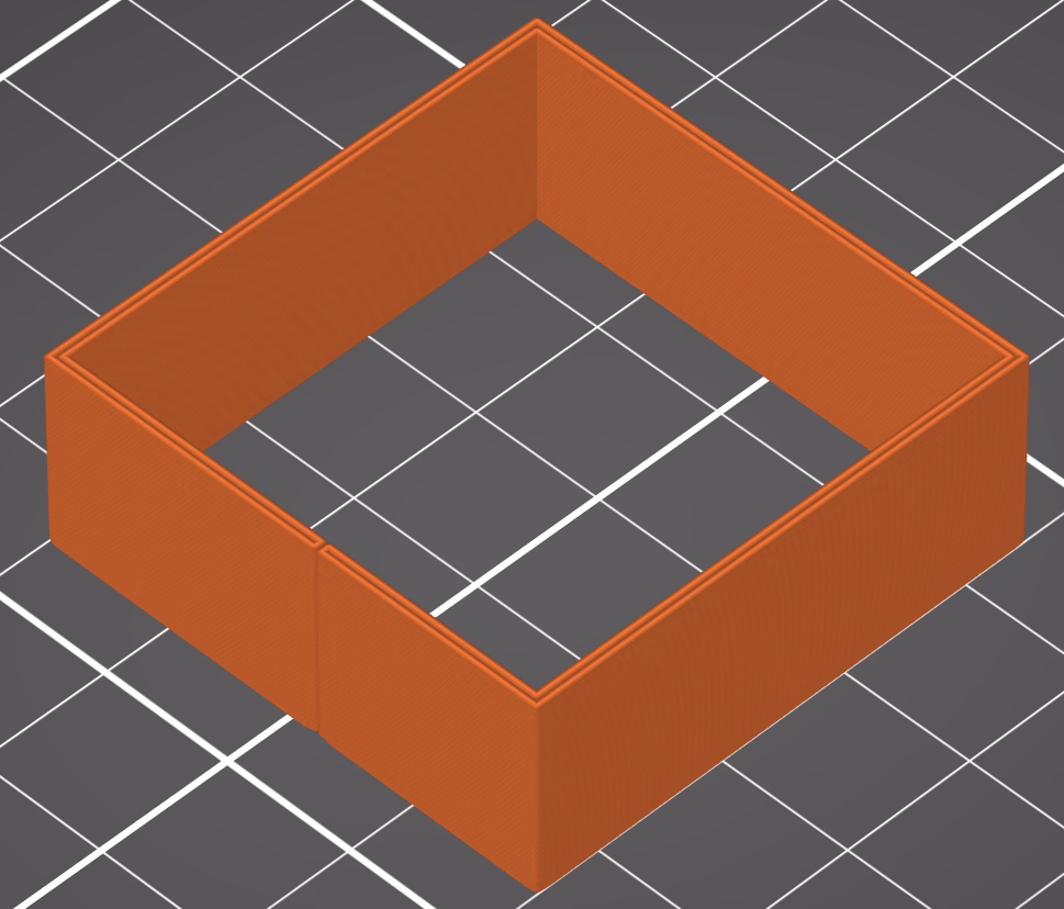
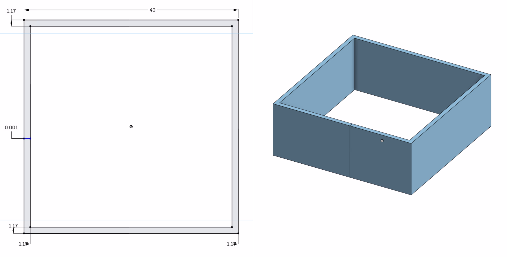
Typically, it gets used for vases and pots. Thus, the name. Here is a crude example (I’m not an aesthetics focused designer, so imagine something prettier than this. If it fits and functions, it ships in my book):
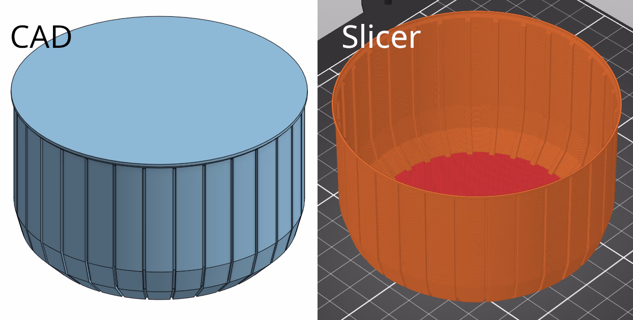
Of note here is that the model itself isn’t hollow, but the slicer will make it hollow for you (since it only prints a single perimeter). In PrusaSlicer this setting is found at “Print Settings” → “Layers and perimeters” → “Vertical shells” → “Spiral vase”. OrcaSlicer etc should have the same or similar setting as well somewhere else. I have no idea about Cura.
But there are some ways to stretch this mode to the limits, and that is what this article is about. This will make vase mode useful for more than just simple vases. And that can often be the fastest and lightest way to print a part, if you can pull it off.
To understand the tricks you do need to understand how vase mode works though. It takes solid geometry, and takes the outline of it. What is inside doesn’t matter. It will be ignored:
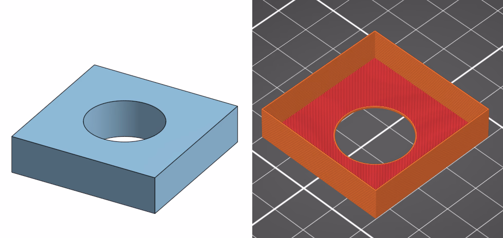
As can be seen, while the hole exists in the bottom solid layers, the slicer ignores it above that point.
So what can we do above that?
Internal geometry via slits
The idea comes from the RC plane 3D printing community, where they want to print lightweight but strong parts. In particular wings with internal supporting geometry.2
There are two main tricks for unconventional vase mode prints. Let’s start with slits, as the next trick builds upon this first trick. As I’m no aircraft wing designer I will use other geometry for illustration purposes. The idea is useful in other contexts than RC wings, that is the whole point of this article.
Make a slit into the part. The left is for demonstration only, you need the slit to be really thin, 0.00011 mm or so, as shown on the right:
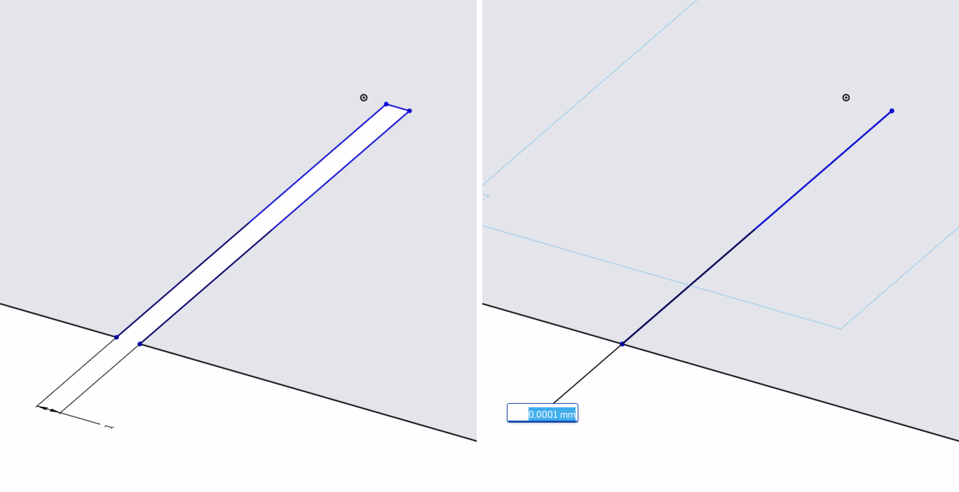
If we extrude this into a block and slice it, PrusaSlicer will see this slit and print an outer perimeter going into the part, making a sort of internal support. You are basically modelling the infill yourself now:
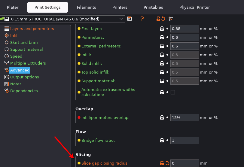
If you try this, it will not work for you. This is because you are missing a crucial setting in PrusaSlicer. By default, PrusaSlicer will merge together close parts of the model. You need to change “Printer Settings” → “Advanced” → “Slicing” → “Slice gap closing radius”. Set it to 0.0.3 Otherwise, none of this will work.
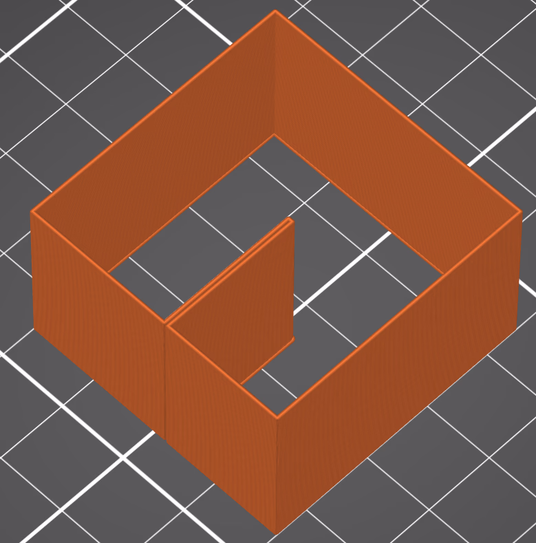
For our example with a hole in the middle from the introduction we could get the following result:
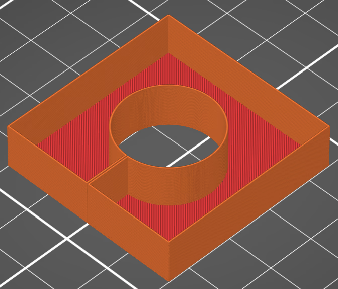
Note that the slit will be visible and you can feel it with your fingers, but it will be a fairly smooth indentation, not a sharp edge.
Double walls
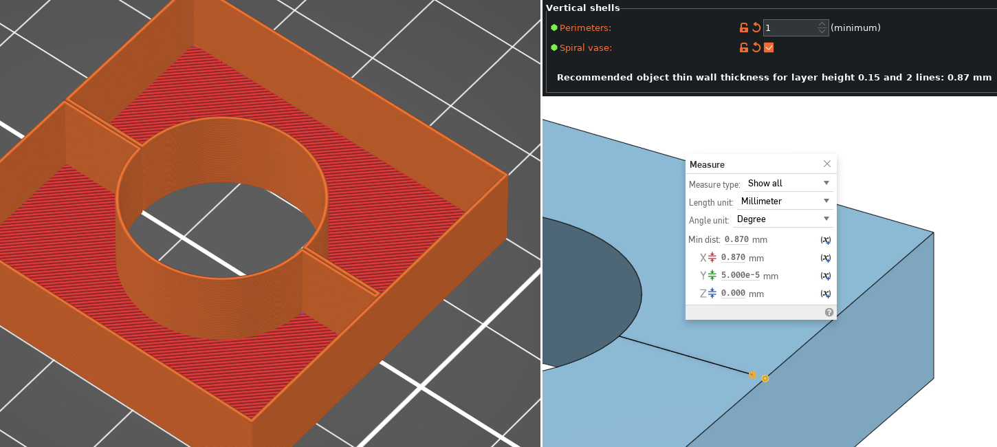
Now, let’s expand on this technique to make it even more useful: Have you ever wanted to use vase mode but with two perimeters? We can build upon the previous trick to make a double wall:
This is done by making a slit through into the hollow inside and making sure the part itself is exactly wide enough for two perimeters that touch. You can find the width you should use by going into PrusaSlicer (with the same settings that you plan to use to print with) and looking at the info text in “Print Settings” → “Layers and perimeters” → “Vertical shells”:
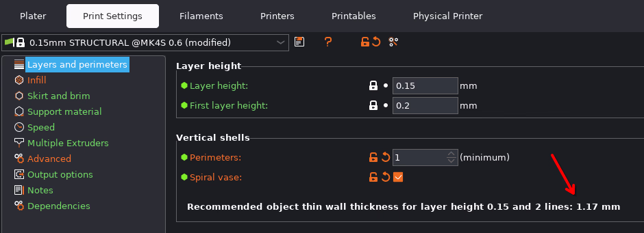
That is the value you want to use for this to work correctly.
We can build upon this to make our internal geometry touch the opposite wall, like so:
We can also use this to anchor a slit to the outside wall. This allows us to anchor internal geometry to the outside wall without poking through. In fact, to ensure we have a single continuous outline, all but one slit must be done like this. The following picture shows what you need to do (note that the double wall thickness is 0.87 mm in this example, it will change depending on other settings):
These two tricks presented so far form the basis of what I have seen called “unconventional vase mode”.4
But there are some more tricks related to vase mode that are worth knowing about.
Extrusion width
To make a vase mode stronger, you can increase the extrusion width. The general recommendation is that you can go to about 2x the nozzle diameter and keep good quality. This works, since the nozzle has a bit of a flat spot around the orifice.
However, British Youtuber “Lost in Tech” did some tests showing that you can go way further than that, but I haven’t tested this myself, and quality does eventually start going down. It might be worth looking into if this is useful to you.
In PrusaSlicer you can change this in “Print Settings” → “Advanced” → “Extrusion width”. For vase mode “External perimeters” is what matters (above the solid base layers, that is):
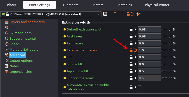
Remember to rescale any double walls to fit the new extrusion width. It might be a good idea to use a variable in your CAD model to make it easier to update (at least if you use parametric CAD like OnShape, FreeCAD or Fusion 360 which support variables).
Fake vase mode
Finally, if you absolutely cannot print something in vase mode you can still get most of the benefits by what I have seen called “fake vase mode”5. To understand this, we should first consider exactly what settings vase mode changes. In PrusaSlicer vase mode changes the following settings:
- Single perimeter (except for the first few bottom layers).
- No top layers.
- No infill (except for the first few bottom layers).
- No supports
- Disables the setting “ensure vertical shell thickness”.
- Prints in a continuous spiral path.
You can do all of those except 6 by hand in the slicer. And you can mix and match those first five things as you see fit.
Let’s investigate this via a case study rather than simplified theoretical examples like we have done so far
Case study: spheres on sticks
I needed some spheres on the end of wooden sticks, to hold up a bird net over my strawberries on my balcony. I didn’t want the net to lie on the plants directly, and I needed something on the end of the sticks so that the net wouldn’t tear. Thus, spheres (or rather: truncated spheres for print bed adhesion and overhang reasons) on sticks.
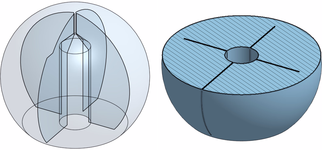
Here is the basic design in a section view:
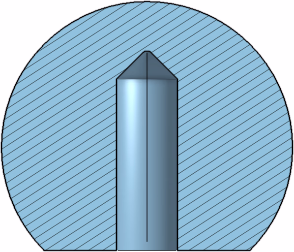
This doesn’t quite work in vase mode, because the top of the sphere has very shallow overhangs. And the top needs to be smooth. (The “roof” of the internal hole is fine, thanks to the cone shape.) It is so close, we can almost use vase mode.
So first I designed this in CAD. We have a slit from the outside to the centre, as well as some slits from the centre that goes almost to the outside. In fact, they go to the “recommended object thin wall thickness” mentioned before. (Note that the slits do not go down into the solid bottom layers, for some additional strength.)
This results in the following in PrusaSlicer:
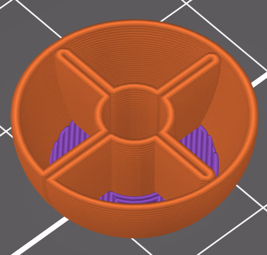
Like true vase mode, I used zero infill. But I enabled “Ensure vertical shell thickness” and 1 top solid layer. This added a tiny bit of material just below the shallow top of the dome, making it printable, but still lighter than printing normally. Then I used a layer range modifier to disable “ensure vertical shell thickness” for the lower part of the print where it wasn’t needed, as PrusaSlicer wanted to add some material on the inside of the lower layers as well.
I also increased the extrusion width to 0.8 mm (with a 0.4 mm nozzle) to get additional strength, and I used scarf seams to make the outside seam almost invisible.
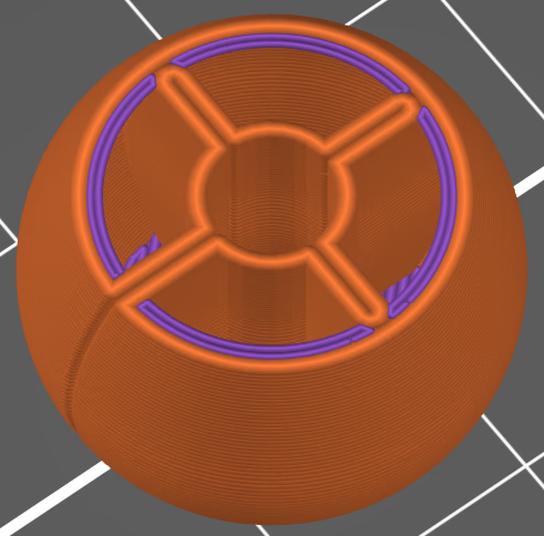
You can go further from true vase mode though: You could have an inner and outer perimeter like traditional non-vase slicing, but still model your own infill only where needed. You will get seams obviously, but you might still be able to print faster and save weight. We are moving further from true vase mode here, but only you can decide what exactly is best for your print:
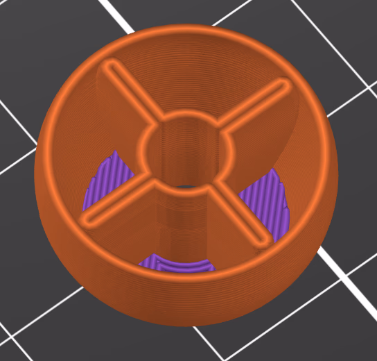
In fact, when I printed some of these spheres, the version without a slit to the outside ended up the best looking6:
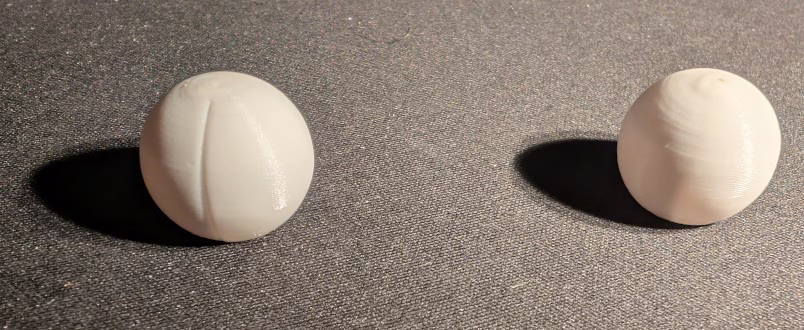
The slit is visible, but on the part printed without a slit extending to the outside there are no visible seams at all. The unevenness at the top is due to me filing away a small blob that the nozzle left behind as it pulled away at the end. It is smooth to the touch but reflects the light differently.
Conclusions
Vase mode and “fake vase mode” is an often underused printing mode for functional parts, and it can be used to save weight and print time. The difference will be most noticeable on larger parts, on smaller parts 10 vs 15 minutes might not be worth the extra design effort (unless you are planning to print many copies of the same part).
I’m a bit disappointed that the slit was as visible from the outside as it was. From the videos about RC aircraft wings that I saw I expected this to be less noticeable. But “fake vase mode” still comes to the rescue here, offering most of the benefits. And when combined with scarf joint seams (which I found truly impressive, first time I tried it), I don’t really see the need for true vase mode any more. You might as well get the best of both worlds.
I did not find any written resource online summarizing these techniques, so I hope this post is useful not just to remind myself in the future, but also to others looking for this information. With that in mind, below is a cheat sheet of the important points and settings to remember.
These techniques require tuning settings in your slicer. This may not be possible if you are printing with at a commercial print farm, or targeting people slicing with a dumbed down web based slicer (as has recently been launched by both Printables and Makerworld). But it would be a shame if such dumbed down slicers restricted what we could design and publish. I will always try to make the most what both CAD and the slicer exposes to me.7
Do you have some other tips or tricks for vase mode? Did I get something wrong? Comment on Reddit or on Lemmy and I will likely see it (eventually).
Cheat sheet
Want to quickly remind yourself of the core ideas of this article when you are designing your next part? Here is a quick cheat sheet:
- Slits: Use slits to add internal geometry.
- 0.0001 mm wide (or 0.001 if your CAD software doesn’t like you that day).
- PrusaSlicer: Set “Print Settings” → “Advanced” → “Slicing” → “Slice gap closing radius” to 0.
- Double walls: Use double walls for more strength and to connect slits to the opposite wall.
- PrusaSlicer: “Print Settings” → “Layers and perimeters” → “Vertical shells” (Look at info text to find width you need to use for your current print settings.)
- Extrusion width: You can increase the extrusion width to 2x the nozzle diameter for additional strength with no quality downsides. You might be able to go even further, but eventually quality will start going down.
- PrusaSlicer: “Print Settings” → “Advanced” → “Extrusion width” → “External perimeters”
- Fake vase mode: You don’t need to use vase mode to get most of the benefits. You can mix and match all parts of normal vase mode except for the continuous spiral path. But consider scarf joints to hide seams.
You might need to experiment with the specific value to make your CAD program and slicer happy. With OnShape, sometimes 0.0001 mm works, sometimes only 0.001 mm works (or Onshape doesn’t see the slit), and I don’t know why exactly. ↩
The first mention I can find of this is in this video by Tom Stanton, but I cannot say for sure that this is where it originated. ↩
I found this solution from this forum post. ↩
Unconventional vase mode is briefly mentioned in this excellent but long blog post about designing for 3D printing. I strongly recommend reading it if you want to make your CAD designs portable between different printers and for general tips on how to design to avoid supports, and in general make full use of the peculiarities of the manufacturing method. ↩
I “semi-invented” this method myself, but then found out I wasn’t first. I was thinking “wouldn’t it be possible to…” and then I googled and found this video by “BV3D: Bryan Vines”, that already discussed this idea, though it takes a while to get to the point. ↩
Printed with AddNorth Economy PETG, white. ↩
I even considered using Full Control XYZ for a minute to have true vase mode and then switch back to non-vase mode on top. In the end I came to my senses and decided not to write my model with Python code. ↩