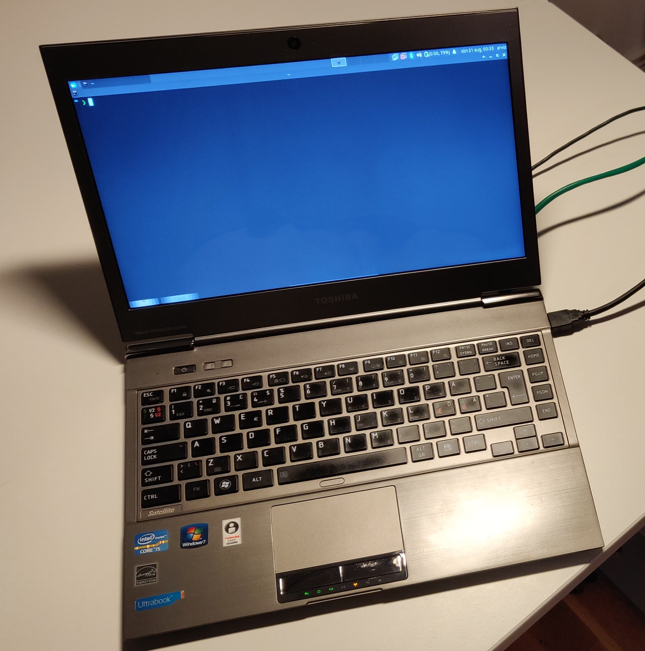
I have inherited a Toshiba Satellite Z830-10W ultrabook. This is a very light and small laptop from around 2011. It had Windows 7 on it. With only 4 GB RAM and a 128 GB mSATA SSD, it is a bit on the weak side for running Windows 10. Plus I’m a Linux user. However, there were issues under Linux.
Initial investigation
Since the form factor and weight was nice (and the battery still had life in it) I decided it might be worth experimenting with. So I booted a USB stick with Xubuntu (not my choice to install, but quick to test out basic features from the live environment). I found several things that did not work: some LEDs, some buttons and backlight breaking after a sleep and resume cycle.
Some may be annoyed at this, but I have been interested in getting into reverse engineering and kernel programming for a long time, so I saw this as an opportunity and good first problem rather than a problem.
At this point I made a list of the problem I knew of so far. I also set up an external SSD with Linux as 128 GB is not enough to work comfortably with both Windows and Linux, and I would need to trace things under Windows to see how they work. I used Arch Linux as that is my Linux distro of choice. The laptop has one USB 3 port, making this approach bearable.
Then I spend some time reading the Linux kernel driver toshiba_acpi that provided some working features to familiarise myself with how ACPI on Toshiba laptops work.
ACPI
A quick summary of ACPI is in order at this point: It is a standard (originally introduced in 1996) that lets the firmware the features of the hardware to the operating system. It is focused on describing things that can not be auto discovered and on power management. For example:
- Addresses of memory mapped chips on the motherboard, such as the CMOS clock.
- How to suspend and turn off the computer.
- Notifications of the lid closing or opening on a laptop.
It also supports vendor specific extensions, and toshiba_acpi implements support for those under Linux. I spent some time reading up on ACPI as well. Some basic functionality is described in fixed format tables. However, most of the complicated features is described by a program that is provided as byte code to the OS. The OS implements a virtual machine that runs the ACPI byte code.
Tooling under Windows
After reading up on relevant background material I needed to figure out what tooling to use on Windows. One thing I quickly discovered was the AMLI debugger. This is bundled with Debugging Tools for Windows and lets you trace ACPI calls when kernel debugging. One snag though: On Windows 7 it needs a “checked build” of the operating system, specifically of ACPI.SYS. I tried to get this working, it did not work out.
I ended up upgrading the laptop to Windows 10. While that is a much worse experience (the laptop takes minutes after boot to become usable, it is completely unusable while updates are downloading or installing, …) I do not plan to keep Windows 10 (or Windows in general) long term. For now, it works.
Using a local kernel debugging session on the Toshiba I was able to execute !amli set traceon spewon. This makes it output a lot of debug info to !dbgprint. A lot. This was way too much to do my intended “press a button, see what happens” approach. I needed to log this to file and compare traces to make any headway finding the needles in the haystacks.
Sysinternals to the rescue! DebugView is a program in the Sysinternals suite of programs that lets me do exactly that (amongst other features).
Side note: User space tracing
I did also investigate the possibility of user space tracing, but that would look at the API between the user space programs and the kernel, which might be relevant, but might use a completely different API that is being translated in the driver. Some tools I came across that might be useful if this is what you want to do:
- API Monitor seems to allow tracing a number of library calls and system calls. In some ways it is comparable to strace on Linux.
- Spy++ is a tool to monitor window messages. It is a part of Microsoft Visual Studio. This might be useful as a complement.
In the end I had a brief look at these tools but did not end up using them for my actual reverse engineering work other than to determine which user space programs and services were talking to the driver (so I could kill all but the one I wanted to investigate at the time and reduce noise). This was really needed as especially the program that pop up an overlay for when you press the Fn-key tended to perform a lot of repeated background queries for the same thing over and over again. And then there is the ECO process that keeps querying for what I believe is power usage all the time (as that seems to be the only thing it is used for). Both of these seem a bit wasteful on the battery in my eyes.
Interestingly, the handling of the extra buttons below by user space was not done via the usual method of DeviceIoControl calls. Instead, this was received as Window event notifications of the WM_POWERBROADCAST type.
The Toshiba driver on for ACPI on Windows is named TVALZ.sys by the way (at least on this particular laptop) in case you want to figure out which processes opens handles to it.
The process: reverse engineering
Next came a tedious task of establishing a baseline with all programs stopped. This involved grepping the various logs on a Linux computer. Then I just had to look at the new logs excluding all those things I filtered out. Each single ACPI function call typically generates hundreds of lines in the log, with details about function parameters and sub calls. Fortunately each new entry point is marked with the line AMLI:. I have included part of one call below as an example. This particular call queries the state of the keyboard backlight. The full log for this call is 168 lines, and as such I have left it out of here!
00015647    10:09:48    AMLI: FFFFD082FA3A2080: \_SB.VALZ.GHCI(Buffer(0x4){
00015648    10:09:48     0x00,0xfe,0x00,0x00},Buffer(0x4){
00015649    10:09:48     0x95,0x00,0x00,0x00},Buffer(0x4){
00015650    10:09:48     0x00,0x00,0x00,0x00},Buffer(0x4){
00015651    10:09:48     0x00,0x00,0x00,0x00},Buffer(0x4){
00015652    10:09:48     0x00,0x00,0x00,0x00},Buffer(0x4){
00015653    10:09:48     0x00,0x00,0x00,0x00})
00015654    10:09:48
00015655    10:09:48    ffffd082f388c1aa: {
00015656    10:09:48    ffffd082f388c1aa: CreateDWordField(Arg0=Buffer(0x4){
00015657    10:09:48     0x00,0xfe,0x00,0x00},Zero,REAX)
00015658    10:09:48    ffffd082f388c1b1: CreateWordField(Arg1=Buffer(0x4){
00015659    10:09:48     0x95,0x00,0x00,0x00},Zero,R_BX)
00015660    10:09:48    ffffd082f388c1b8: And(REAX,0xff00,Local0)=0xfe00
00015661    10:09:48    ffffd082f388c1c1: If(LEqual(Local0=0xfe00,0xfe00)=0xffffffffffffffff)
00015662    10:09:48    ffffd082f388c1c9: {
00015663    10:09:48    ffffd082f388c1c9: If(LEqual(R_BX,0xc000)=0x0)
00015664    10:09:48    ffffd082f388c1e1: If(LEqual(R_BX,0xc800)=0x0)
00015665    10:09:48    ffffd082f388c1f9: If(LEqual(R_BX,0xc801)=0x0)
00015666    10:09:48    ffffd082f388c211: }
00015667    10:09:48    ffffd082f388c211: If(LEqual(Local0=0xfe00,0xff00)=0x0)
00015668    10:09:48    ffffd082f388c248: Return(GCH0(Arg0=Buffer(0x4){
00015669    10:09:48     0x00,0xfe,0x00,0x00},Arg1=Buffer(0x4){
...
The log consists of line number, time stamp and log text. The log text contains some decompiled ACPI byte code (known as ACPI Machine Language or AML for short). AML defines both a nested structure of objects and methods, but also the instructions in those methods.
The process: testing your hypotheses
Once I had a set of hypotheses based on the reverse engineering I had done I needed to test them. One way would be to actually change to Linux kernel driver, recompile it and then reload it via rmmod and insmod (or using modprobe).
However, a much quicker option is to use acpi_call. This is a out of tree kernel module that allows the root user to do direct ACPI method calls from the comfort of their own shell prompt. I ended up using the following helper functions in my zsh prompt to test these:
call_ghci() {
  echo "\\_SB_.VALZ.GHCI $1 ${2:-0} ${3:-0} ${4:-0} ${5:-0} ${6:-0}" | \
    tee /proc/acpi/call
  cat /proc/acpi/call; echo
}

set_hci() { call_ghci 0xff00 "$@" }
get_hci() { call_ghci 0xfe00 "$@" }
get_sci() { call_ghci 0xf300 "$@" }
set_sci() { call_ghci 0xf400 "$@" }
open_sci() { call_ghci 0xf100 "$@" }
close_sci() { call_ghci 0xf200 "$@" }
Some example usages:
$ # Turn on ECO LED
$ set_hci 0x97 1 1 0 0 0
\_SB_.VALZ.GHCI 0xff00 0x97 1 1 0 0
[0x0, 0x97, 0x1, 0x1, 0x0, 0x0]

$ # Get the BIOS boot order
$ open_sci; get_sci 0x157 0 0 0 0 0; close_sci
\_SB_.VALZ.GHCI 0xf100 0 0 0 0 0
[0x44, 0x0, 0x0, 0x0, 0x0, 0x0]
\_SB_.VALZ.GHCI 0xf300 0x157 0 0 0 0
[0x0, 0x8505, 0xfff30174, 0x5, 0xfff30741, 0x0]
\_SB_.VALZ.GHCI 0xf200 0 0 0 0 0
[0x44, 0x0, 0x0, 0x0, 0x0, 0x0]
This allowed me to test almost all the features without changing kernel code. The one exception is the notifications for the buttons
Some other tooling that may be useful to know about under Linux is that many (but not all) ACPI events are sent to user space via Netlink. I found that the pyroute2 library allowed me to read this without resorting to coding in C.
The documentation was lacking for this particular feature of pyroute2, but that has since been fixed.
In the end reading the ACPI events over netlink was not useful to me. The things I needed were not there.
Results
In this section I present my findings. This is organised to help someone who wants to work on this, or perhaps extend my work. It is not for a general audience, but is intended as reference material for anyone working on kernel development in this area, or intending to improve Linux support for similar devices.
Background on Toshiba ACPI communication methods
This section is a short summary of the general protocol. This is already implemented in the toshiba_acpi Linux kernel driver. If you are already familiar with that you can skip this section.
Almost all vendor specific features work via the \_SB_.VALZ ACPI device defined in the DSDT. This device is also known as TOS6208 and VALZeneral. There are a handful of interesting methods on this object, but for the purposes of this write-up only GHCI is relevant. This method takes 6 integer (32-bit) arguments and returns a buffer 6 32-bit integers.
The general format of queries is: {OPERATION, REGISTER, ARG1, ..., ARG4 }. The operation is one of HCI_GET/HCI_SET or SCI_GET/SCI_SET (plus SCI_OPEN and SCI_CLOSE). This allows for getting and setting various registers to control features or read out data.
The data returned varies a bit, but is generally on the form: {STATUS_CODE, REGISTER_FROM_QUERY, VAL1, ..., VAL4 }
What is the difference between HCI_* and SCI_* calls? The only important difference here is that for SCI_GET/SCI_SET you first need to call SCI_OPEN and then follow the get or set with a SCI_CLOSE call.
Much of the rest of this write-up consists of documenting registers previously not handled by the toshiba_acpi Linux driver.
The “Eco” LED

The toshiba_acpi driver has support for controlling some LEDs including the “Eco” LED (the eco LED is the one on the far right in the picture). Unfortunately that LED works differently on this laptop.
Apparently Toshiba has two formats for controlling this on differet laptops:
// Format A
{HCI_SET, HCI_ECO_MODE, onoff, 0, 0, 0}
// Format B
{HCI_SET, HCI_ECO_MODE, onoff, 1, 0, 0}
The toshiba_acpi driver tries to use format B if it gets the error TOS_INPUT_DATA_ERROR when trying to use format A. On this laptop the error returned is TOS_NOT_SUPPORTED. Other than that format B works as expected.
Battery charge mode
This laptop supports not charging the battery fully in order to prolong battery life. Unlike for example ThinkPads where this control is granular here it is just off/on. When off it charges to 100%. When on it charges to about 80%.
According to the Windows program used to control the feature the setting will not take effect until the battery has been discharged to around 50%. On Windows Toshiba branded this feature as “Eco charging”
In the following example ACPI calls I will use the following newly defined constants:
#define HCI_BATTERY_CHARGE_MODE 0xba
#define BATTERY_CHARGE_FULL 0
#define BATTERY_CHARGE_80_PERCENT 1
- To set the feature:
{HCI_SET, HCI_BATTERY_CHARGE_MODE, charge_mode, 0, 0, 0} - To query for the existence of the feature:
{HCI_GET, HCI_BATTERY_CHARGE_MODE, 0, 0, 0, 0} - To read the feature:
{HCI_GET, HCI_BATTERY_CHARGE_MODE, 0, 0, 0, 1}
The read may need to be retried if TOS_DATA_NOT_AVAILABLE is returned as the status code. This rarely happens (never observed it on Linux), but I have seen it happen under Windows, and the Windows software it did retry it.
Panel power control via HCI
The toshiba_acpi driver supports controlling the panel power via SCI calls (SCI_PANEL_POWER_ON). This laptop appears to support that (the codes give no errors), but nothing happens. Instead, HCI calls must be used.
#define HCI_PANEL_POWER_ON 0x2
#define PANEL_ON 1
#define PANEL_OFF 0
- To read/query existence:
{HCI_GET, HCI_PANEL_POWER_ON, 0, 0, 0, 0} - To write:
{HCI_SET, HCI_PANEL_POWER_ON, panel_on, 0, 0, 0}
Hardware buttons
All the Fn+<key> hotkeys work. However, there are some hardware buttons that do not. These buttons are:
- A button between space and the touchpad to turn off/on the touchpad.
- Two buttons next to the power button, one is “eco-mode”, the other is “projector”.


The two buttons next to the power button both send Windows+X by default. The touchpad control button does nothing that Linux can detect.
To enable this functionality several changes are needed.
The toshiba_acpi driver currently uses {HCI_SET, HCI_HOTKEY_EVENT, HCI_HOTKEY_ENABLE, 0, ...} to enable the Fn+<key> hotkeys, where HCI_HOTKEY_ENABLE = 0x09. However on this laptop the value 0x05 must be used instead.
This is not the whole story however, as these keys do not work like any of the Fn-hotkeys (ACPI notification on \_SB_.VALZ). Instead, once enabled via the above method they start sending notifications on various PNP0C32 devices. These are currently not handled by Linux. According to a search PNP0C32 is “HIDACPI Button Device”.
The devices in question are:
PNP0C32 \_SB_.HS81 UID 0x03: Enable/disable trackpadPNP0C32 \_SB_.HS87 UID 0x01: Eco buttonPNP0C32 \_SB_.HS86 UID 0x02: Monitor/projector button
Only the “path” and the UID value in the ACPI DSDT tell these devices apart.
The notification always uses the value 0x80.
BIOS setting control from the OS
Several of the BIOS settings can be controlled from the OS. This all happens via SCI calls. On Windows the Hwsetup.exe program offers this control. I’m not sure how useful any of this is (as this is already available via the BIOS).
Still: it is a neat feature to have.
Setting boot order
This is a BIOS (not UEFI) laptop, so boot order could normally not be controlled from the OS. However here it is possible:
#define SCI_BOOT_ORDER 0x157
In this SCI register the boot order is stored as a list with each nibble indicating a device:
#define SCI_BOOT_ORDER_FDD 0x0
#define SCI_BOOT_ORDER_HDD 0x1
#define SCI_BOOT_ORDER_LAN 0x3
#define SCI_BOOT_ORDER_USB_MEMORY 0x4
#define SCI_BOOT_ORDER_USB_CD 0x7
#define SCI_BOOT_ORDER_USB_UNUSED 0xf
These are then combined as follows:
For example, consider the request to set boot order to USB memory, USB CD, HDD, LAN, FDD: {SCI_SET, SCI_BOOT_ORDER, 0xfff03174, 0, 0, 0}
Each nibble indicates a device, with the lowest nibble being the first device in the boot order. As this device doesn’t have a physical FDD I assume that this refers to USB attached devices, but I have not tested this (I do have a USB floppy drive if anyone really cares).
When reading the data out the result is a bit surprising: {0x0, 0x8505, 0xfff30174, 0x5, 0xfff30741, 0x0}
Presumably these other values also mean something, the boot order in this case is USB memory, USB CD, HDD, FDD, LAN, so the third value is the boot order.
Setting USB memory emulation
The BIOS can either treat USB memories as HDDs or FDDs for booting purposes:
#define SCI_BOOT_FLOPPY_EMULATION 0x511
#define SCI_BOOT_FLOPPY_EMULATION_FDD 0x1
#define SCI_BOOT_FLOPPY_EMULATION_HDD 0x0
- To set:
{SCI_SET, SCI_BOOT_FLOPPY_EMULATION, value, 0, 0, 0} - Getting/existence query:
{SCI_GET, SCI_BOOT_FLOPPY_EMULATION, 0, 0, 0, 0}
Display during boot
This controls if BIOS/GRUB/etc is shown on just the internal monitor or not.
Note: When changing this in Windows it tells me a restart is required.
#define SCI_BOOT_DISPLAY 0x300
#define SCI_BOOT_DISPLAY_INTERNAL 0x1250
#define SCI_BOOT_DISPLAY_AUTO 0x3250
- To set:
{SCI_SET, SCI_BOOT_DISPLAY, value, 0, 0, 0} - Getting/existence query as usual.
CPU control
I presume this is only for operating systems that don’t manage this themselves, I don’t know for sure. The wording in the documentation is vague, but I believe it controls CPU frequency behaviour.
Note: When changing this in Windows it tells me a restart is required.
#define SCI_CPU_FREQUENCY 0x132
#define SCI_CPU_FREQUENCY_DYNAMIC 0x0
#define SCI_CPU_FREQUENCY_HIGH 0x1
#define SCI_CPU_FREQUENCY_LOW 0x2
Set and get as usual: {SCI_GET/SET, SCI_CPU_FREQUENCY, value, 0, 0, 0} (You should be spotting a pattern by now.)
Wake on LAN (WoL)
Note! This only controls Wake on LAN when off/hibernated (and since this laptop has Intel Rapid Start, presumably in that mode too). It is not relevant to WoL when in sleep.
Here the Windows driver seem to query several possibilities until it hits on one that works:
#define SCI_WAKE_ON_LAN 0x700

#define SCI_WAKE_ON_LAN_OFF 0x1
#define SCI_WAKE_ON_LAN_ON 0x1

#define SCI_WAKE_ON_LAN_REG1 0x0
#define SCI_WAKE_ON_LAN_REG2 0x1000
#define SCI_WAKE_ON_LAN_REG3 0x800
- To set:
{SCI_SET, SCI_WAKE_ON_LAN, value | register, 0, 0, 0} - To get/query:
{SCI_GET, SCI_WAKE_ON_LAN, register, 0, 0, 0}
For example on this specific laptop to enable WoL:
{SCI_SET, SCI_WAKE_ON_LAN, SCI_WAKE_ON_LAN_ON | SCI_WAKE_ON_LAN_REG3, 0, 0, 0}
REG1 and REG2 give return code TOS_INPUT_DATA_ERROR on this laptop, but presumably they are needed on some laptops, or the Windows program would not be attempting to use them.
SATA power control
This is another one that I don’t know what exactly it corresponds to, maybe it is something Linux can control directly:
#define SCI_SATA_POWER 0x406
#define SCI_SATA_POWER_BATTERY_LIFE 0x1
#define SCI_SATA_POWER_PERFORMANCE 0x0
Get/set/query as expected: {SCI_SET, SCI_SATA_POWER, value, 0, 0, 0}
Legacy USB
Controls Legacy USB support in BIOS.
Note: When changing this in Windows it tells me a restart is required.
#define SCI_LEGACY_USB 0x50c
#define SCI_LEGACY_USB_ENABLED 0x1
#define SCI_LEGACY_USB_DISABLED 0x0
Get/set/query as expected: {SCI_SET, SCI_LEGACY_USB, value, 0, 0, 0}
Wake on keyboard
This controls if pressing a key on the keyboard wakes the laptop from sleep. Otherwise, only opening the monitor or pressing the power button works for this.
#define SCI_WAKE_ON_KEYBOARD 0x137
#define SCI_WAKE_ON_KEYBOARD_ENABLE 0x8
#define SCI_WAKE_ON_KEYBOARD_DISABLE 0x0
Get/set/query as expected: {SCI_SET, SCI_WAKE_ON_KEYBOARD, value, 0, 0, 0}
Other features
Here is a summary of other features that I have not been fully able to decode and understand.
Power usage
The Windows-software can read power usage in watts both when on AC and when on battery.
On startup of the program for this and when switching between AC and battery:
{HCI_SET, 0x42, 0x1, 0, 0, 0}{HCI_SET, 0x42, 0x10, 0, 0, 0}
When on AC the following calls are involved:
{HCI_GET, 0xa7, 0x0, 0x0, 0x8b, 0x0}{HCI_GET, 0xa7, 0x0, 0x0, 0x8b, 0x1}{HCI_GET, 0xa8, 0x1, 0x0, 0x98, 0x0}{HCI_GET, 0xa8, 0x1, 0x0, 0x98, 0x1}
When on battery the calls changes:
{HCI_GET, 0xa1, 0x1, 0x0, 0x44, 0x0}{HCI_GET, 0xa1, 0x1, 0x0, 0x44, 0x1}{HCI_GET, 0xa8, 0x1, 0x0, 0x98, 0x0}{HCI_GET, 0xa8, 0x1, 0x0, 0x98, 0x1}
Not all of these calls happen with the same frequency. The frequency also changes when going between AC and battery.
The returned data makes no sense to me, but it does vary with system load, so I suspect scaling and possibly masking is involved. However, I don’t have a good way to go any further with this without going into questionable methods such as decompilation. As such I have left this alone for now.
Mysterious other calls
I don’t even know what these do, but I have observed them under Windows:
When locking the screen under Windows: {HCI_SET, 0x25, 0x2, 0x1, 0, 0} When putting the system to sleep under Windows: {HCI_SET, 0xbd, 0x81, 0, 0, 0}
Linux currently only uses HCI_GET on HCI_SYSTEM_INFO, Windows sometimes uses HCI_SET too:
- On screen lock:
{HCI_SET, HCI_SYSTEM_INFO, 0, 1, 0, 0} - On screen unlock:
{HCI_SET, HCI_SYSTEM_INFO, 0, 0, 0, 0}
Toshiba Service Station causes this call to be performed once when it is opened:
{HCI_GET | 0x12, 0x9f, 0, 0, 0, 0}
The 0x12 makes no difference, but seems to be returned in the reply buffer. Thus, I speculate that the lower byte can be used as a sort of “transaction ID” to associate a request with a response. As to what the call does I can’t say, but it returns the same value (0x5988 in 4th integer in the buffer) every time.
In addition, on Windows, may calls that just fail (according to the status codes) are performed. These presumably are calls relevant to other models.
What’s next?
Now that everything is documented, and everything except the buttons tested, what is the next step?
At this point is I plan to experiment changing the toshiba_acpi kernel driver. For implementing support for the hardware buttons I plan to contact the relevant mailing list as I’m unsure how to proceed. Is a Toshiba specific driver a good option or is a generic driver better?